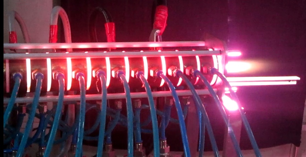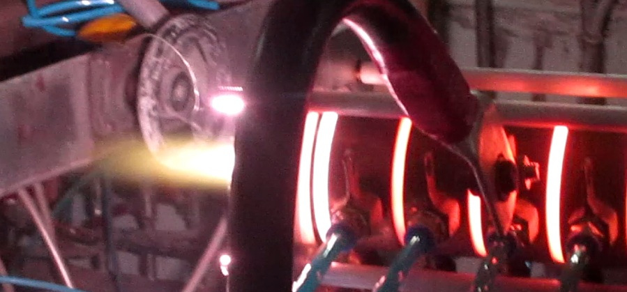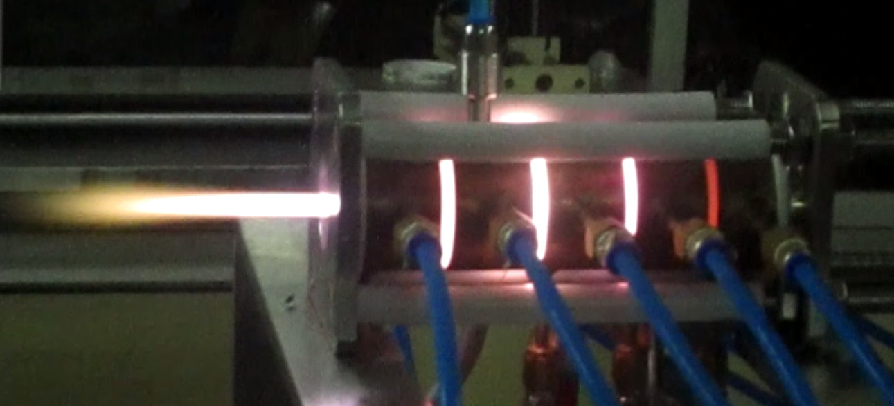

A compact tungsten electrode argon plasma torch operating in the range of 5 kW-50 kW is developed by BARC for high temperature plasma processing and available for transfer of technology to industry. It takes commercially available argon and converts that into controlled well defined cylindrical jet of plasma with a maximum core temperature around 10000K to 20000K depending on operating conditions. It offers an electro-thermal efficiency of 50% or more. The device produces plasma in the form of an intensely luminous extremely hot radiating atmospheric pressure cylindrical plasma jet controlled in terms of its length, diameter, velocity and power content. The plasma jet facilitates a very high enthalpy inert environment to engineer variety of process chemistries, possible only at highly reactive extremely high temperature plasma environment offered by the jet.
A compact tungsten electrode argon plasma torch operating in the range of 5 kW-50 kW is developed for high temperature plasma processing and available for transfer of technology to industry. It takes commercially available argon and converts that into controlled well defined jet of plasma with a maximum core temperature around 10000K and electro-thermal efficiency around 50% or more. The device produces plasma in the form of an intensely luminous extremely hot radiating atmospheric pressure cylindrical plasma jet controlled in terms of its length, diameter, velocity and power content. The plasma jet facilitates a very high enthalpy inert environment to engineer variety of high temperature process chemistry depending on reactants.
A thermal plasma jet of argon is a beam of huge concentrated thermal energy at very high temperature consisting of electrons, argon ions and neutrals. Such plasmas are naturally formed in atmosphere during thunderbolt and observed as a bright flash in the sky. Similar plasma is produced by the offered technology in the form of an intensely luminous extremely hot radiating atmospheric pressure cylindrical plasma jet controlled in terms of its length, diameter, velocity and power content using a small device called argon plasma torch. The novel technology offers a compact device that takes argon gas from a cylinder bank and converts it into a controlled well defined jet of argon plasma at an electrical power level of many tens of kW with efficiency greater than 50%. Low device cost, low operational cost, simple design, use of cheapest gas (argon), good efficiency (>50%), high temperature (~10000 K at the anode exit) and ease of control are some of the key features of the technology. .
Internal components of the device are shown in Figure 2. The torch has adjustable, modular, segmented design. The same device can be adopted for variety of applications requiring different power levels of operations and process needs. It has one cathode segment, one auxiliary anode segment adjacent to it, one main anode segment at the exit end and floating segments in between. The plasma cathode is the source section that holds a 2% thoriated tungsten cathode along the central axis and gas injection ports surrounding it. The cathode is base cooled and emits electrons under thermionic emission. A coolant header supplies chilled water to all the segments. With the help of a radio-frequency igniter, the plasma (arc) is initiated in this section between the cathode and the auxiliary anode. Once the source is on, the arc is transferred to the subsequent sections and finally to the anode. The role of the intermediate segments is to streamline the plasma jet as well as develop appropriate voltage in the plasma column for operation at a given power level. For a given current and gas flow rate, the power of the plasma jet can be adjusted just by changing the length of this constrictor section. An extremely bright well-formed huge jet comes out from the device as shown in Fig.2.
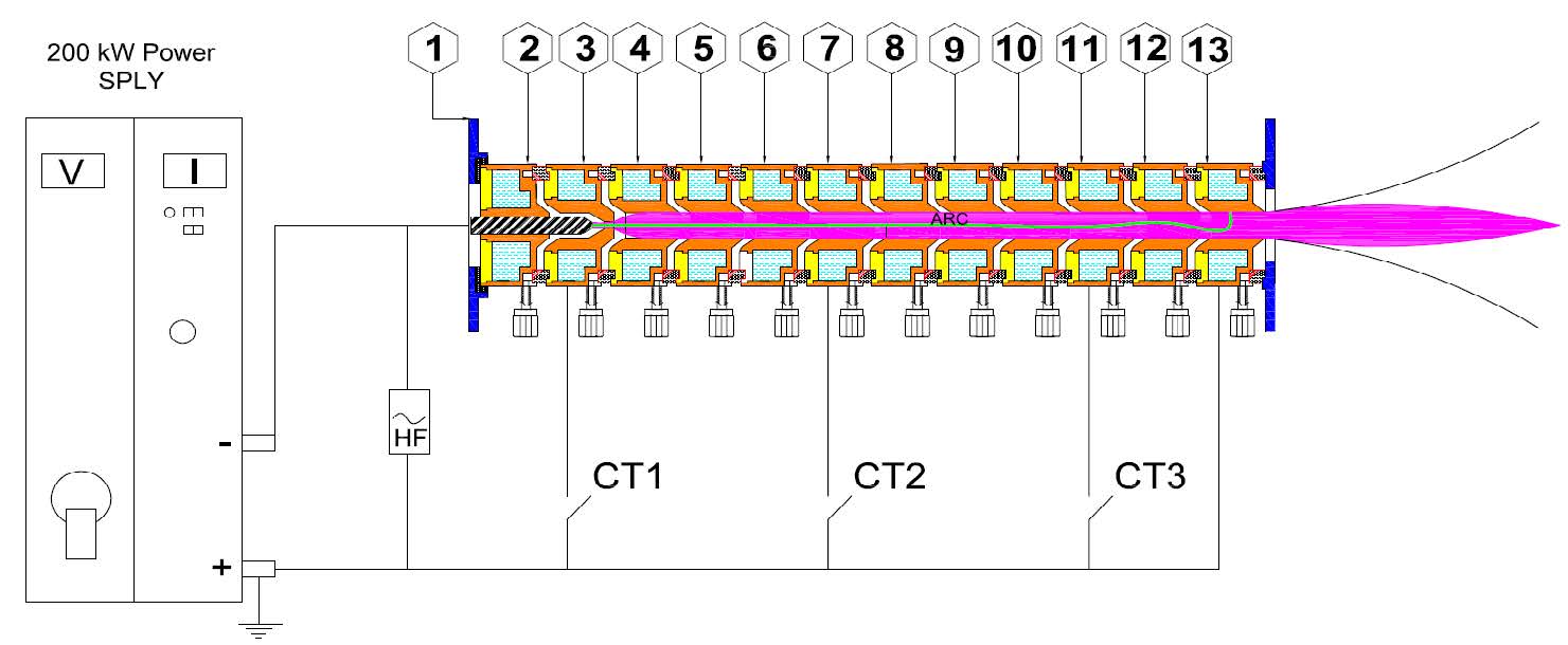
Electrical connection and principle of operation of the torch are explained in Fig.3. A DC constant current power supply operates the plasma torch. Details of the required power supply are provided in the next section. Numbers of segments to be used in the torch are completely customized. The torch in Fig.3 is having 12 segments, electrically isolated from each other through Teflon insulator rings. Each of insulator ring has 25 equi-spaced gas injection ports of id 1mm along its periphery, which allow gas to be injected in the space between two adjacent rings. Segment '3' (auxiliary anode), segment '7' and segment '11' are connected with the main anode (segment '13') via high current contactors, namely, CT1, CT2 and CT3. Initially all the contactors are set in on position. Argon at a rate of 40 slpm is injected between segment '2' and segment '3'. To ignite the arc, momentarily a high frequency high voltage pulse (3 MHz & 3 kV) is applied between segment '2' (cathode) and segment '3'. Applied radio frequency pulse causes breakdown of the flowing argon gas. Already existing bias establishes an arc between the cathode and the auxiliary anode. Current is increased and CT1 is opened. This forces the arc to get connected to segment '7'. Current is increased further and CT2 is opened. This forces the arc to get connected to segment '11'. Desired final current (~400A) is set and lastly the contactor CT3 is opened. This establishes the final arc connection between cathode and the main anode (segment '13'). Typical arc voltage drop per segment is around 25 V. A total voltage drop of ~300V is expected. Total operating power reaches ~120 kW (400 x300=1200W). Operating current may be adjusted appropriately for operation at a desired power level. For generating plasma of any other gas like argon, nitrogen, CO2, CH4, H2O etc., the desired gas may be injected downstream through the gas injection ports.
The complete plasma system consists of the following five subsystems:
| 1 | The argon plasma torch serves as the key device for the entire system. Rests of the units are the supporting components for the torch. |  |
| 2 | An IGBT based DC power supply delivers the necessary power for the torch operation |  |
| 3 | The argon gas supply system, consisting of a bank of commercial argon gas cylinders, supplies the necessary argon flow for the torch operation. |  |
| 4 | The chilled water supply system provides necessary cooling for the thermally stressed components of the plasma torch. | 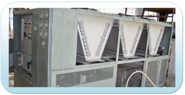 |
| 5 | The ignition and the control system consist of an HF (high frequency) unit, three contactors and a power supply control unit. The HF unit (included in the power supply) ignites the arc, the contactor units transfer the arc to the main anode and the Power supply control unit controls the delivered power to the torch through control of arc current. | 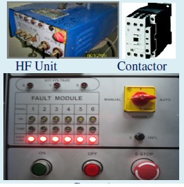 |
| 1 | Voltage-Power Characteristics :Achieved typical voltage-power characteristic for the plasma torch is shown in the adjacent Table. The arc voltage remains nearly constant over a range of currents. A slight drop in the voltage is observed at higher currents. Increase in power with increase in current is slightly non-linear. For operation around 50 kW the torch operates near current 250 A and voltage 231 V |

Voltage-Power Characteristics
|
| 2 | Cathode performance :Extremely low electrode (thoriated tungsten) loss due to erosion is observed for the cathodes. |
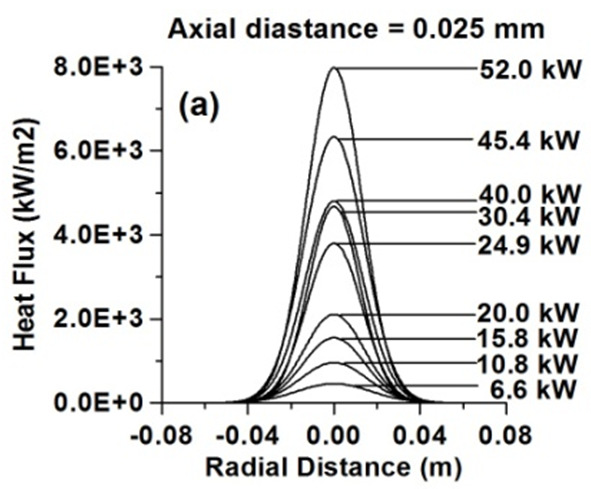
Fig.6. Typical heat flux profile
|
| 3 | Efficiency and Thermal Losses :Power delivered to the generated plasma by the power supply is partly dissipated in heating the segments and lost in the cooling water. Rest of the delivered power goes into the plasma. Efficiency is estimated as the power that goes into the plasma compared to the total electrical power input. After the source section, depending on power of operation, the expanding plasma is entrained by the cold wall of the segments in-between. At lower power the expansion is less and the heating of the constrictor wall by the plasma is not much. However, at very high power, plasma is closer to the segment wall and it heats the constrictor resulting in a drop in efficiency. Typically, less than 5 % of the total electrical power is dissipated by the cathode. The torch efficiency is usually 50% or more at around 50 kW in non-transferred mode. In the transferred arc mode efficiency may be higher than 80%./td> | 
Fig.7. Arc voltage vs number of segments
used (I=200A)
|
| 4 | Heat flux, arc voltage and segments used :Figure 6 presents typical heat flux profiles measured using double calorimeter under different power levels of operation. Variation of arc voltage as a function of number of segments and discharge gap are presented in Fig.7 anf Fig.8 respectively. |
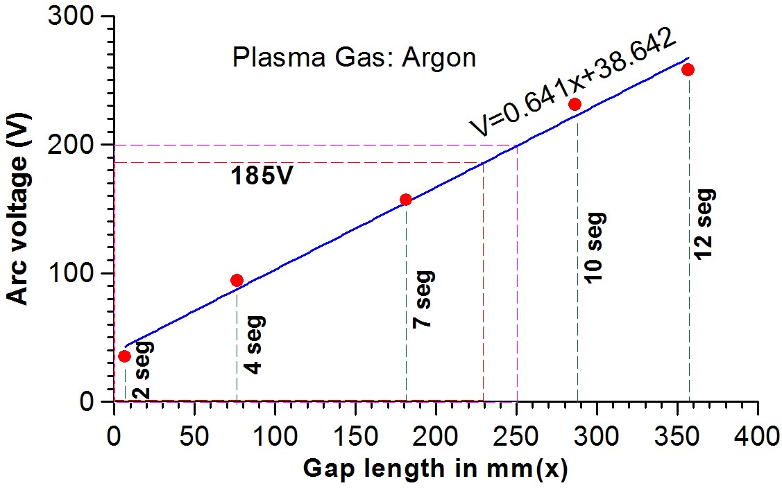
Fig.8. Arc voltage vs discharge gap length
(I=200A)
|
| 5 | Typical temperature at the nozzle exit :Temperature at the exit of the plasma torch is determined using Boltzmann plot technique. Intensity of the emitted argon lines were noted for determination of plasma temperature. A temperature around 8800K is observed near 50 kW. |
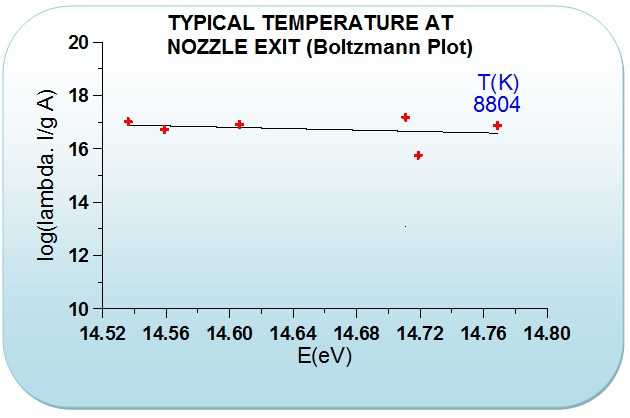
Fig.10. Determination of temperature at
the nozzle exit using Boltzmann Plot
Technique
|
Instrumentation & Control
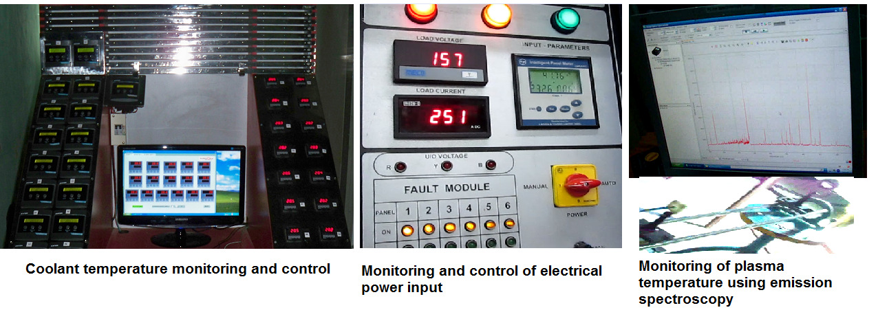
For operation of the plasma torch, the control console performs ignition of the arc, control of the arc current, transfer of the arc to the main anode through the contactors, control of plasma gas flow, control of coolant water flow, control of coolant water temperature, monitoring of plasma temperature, monitoring of arc voltage, monitoring of supply line voltages and emergency stop. The inlet coolant temperature is automatically controlled by a chiller unit at the set temperature value. IGBT based power supply energizing the torch includes RF igniter within it. Necessary interlocks to block RF to protect other electronic components while ignition and coolant flow for IGBT are included in the power supply unit. A computer based ocean- Optics spectrometer remotely scans the spectrum emitted from the plasma using a fiber and lens arrangement and stores the data in the computer for offline analysis. A safety interlock assures coolant flow before the power supply is turned on.
OPERATION
Typical operation of the plasma torch at current beyond 150A results in a huge plasma jet. JxB thruster principle is utilized to produce the long jet of plasma while maintaining flow rate of gas. Typical plasma gas flow is 18 standard liter per minute of argon. Total coolant water flow for removal of heat from thermally stressed components is around 25 litre per minute for operation at 50 kW. The torch has provision for auxiliary gas entry at every segment: The torch can run without any problem even if no gas is fed into these additional ports. Plasma temperature achieved under such conditions is measured to be around 11000 K at the nozzle exit.
However, additional injection of gasses at the additional ports lowers temperature of the plasma, increases voltage of the arc, increases power input to the plasma, decreases thermal load to the components and significantly raises efficiency of the device. Unfortunately, for increased flow rate, the arc gets thermally constricted due to thicker cold boundary layer and prefers constricted attachment with the anode rather than diffused connection. Once constricted connection is established, enormous heat flux is dumped over the arc spot of area few mm2 and the anode is prone to puncture unless arc root rotation is forced by employing external magnetic field. Therefore, for operation without external magnetic field at higher power, low flow rate of plasma gas is safe. However, for applications that can function at lower temperatures, a jet of much higher efficiency may be obtained by employing a higher gas flow rate with a longer anode fitted with magnetic field coil.
Technical Data Sheet
| Diameter | 72 mm |
| Length | 70 mm (5kW)- 350mm(50kW) |
| Plasma exit bore | 10mm - 15 mm |
| Coolant connector | 1/4 inch BSP |
| Gas connector | 1/4 inch BSP |
| Electrical connector type | Plate type with central bore (10 mm) |
| Cathode type | Rod type thoriated tungsten |
| Anode type | Electrolytic copper |
| Segment cooling | Annular channel flow (15 lpm water) |
| Type & Line supply | Output constant current supply: [Input electrical line supply: 50Hz(±5%), 3 phase AC] |
| Open circuit voltage | 450 V |
| Maximum current | 500 A |
| Current ripple | <5% of supply current |
| Control knobs |
|
| Indicator |
|
| Type | Commercial argon cylinder bank |
| Capacity | 50 standard liter per minute @4.5 bar |
| Discharge pressure | Work: 4.5 kg/cm2 Max: 7.5 kg/cm2 |
| Filter ripple | Oil content <2 ppm Moisture content < 1ppm |
| Type | Outdoor, weather proof, Industrial process cooling system |
| Capacity | 120 liter per minute at 7 kg/cm2 of pressure |
| Inlet & outlet temperature | Inlet: 30-50 C Outlet: 15-30 C |
| Storage tank | Capacity 500 liter |
| Control and display |
|
| HF ignition | 3 kV 3 MHz |
| Diagnostic Spectrometer | Spectral range: 400 nm to 480 nm Resolution: 0.05nm |
| RTD sensor | Range:0-100 °C Resolution: 0.1°C |
| Coolant Rotameter | Range: 0-30 lpm |
| Gas flow meters | Range: 0-100 lpm |
Ref.1. Caroline Ducharme, "Technical and economical analysis of Plasma-assisted Waste-to-Energy processes", M.S. Thesis, Dept. earth and Environmental Engineering, Columbia University, 2010.
Capacity, Investment & Unit Cost of Production

